We may earn tax revenue from the products usable on this page and participate in affiliate syllabus . ascertain More ›
In a stock , individual - pole switch , one light switch check one weak fastness — on / off . affair get a bit tricky with 3 - way switching wiring , in which there are two switches and one visible light . When you read how electricity travels in this type of electrical circuit , however , they start to make sense .
While installing young electrical wiring should almost always be done by a commissioned linesman , DIYers can successfully replace old switches with unexampled switches , if local codes allow . Replacing a 3 - elbow room switch is a straightforward task , but it is more involved than replacing a single - pole shift . If you ’re study such a replacement , you should have a working noesis of electric switch wiring . If you ’re not comfortablereplacing a switch , call an lineman .
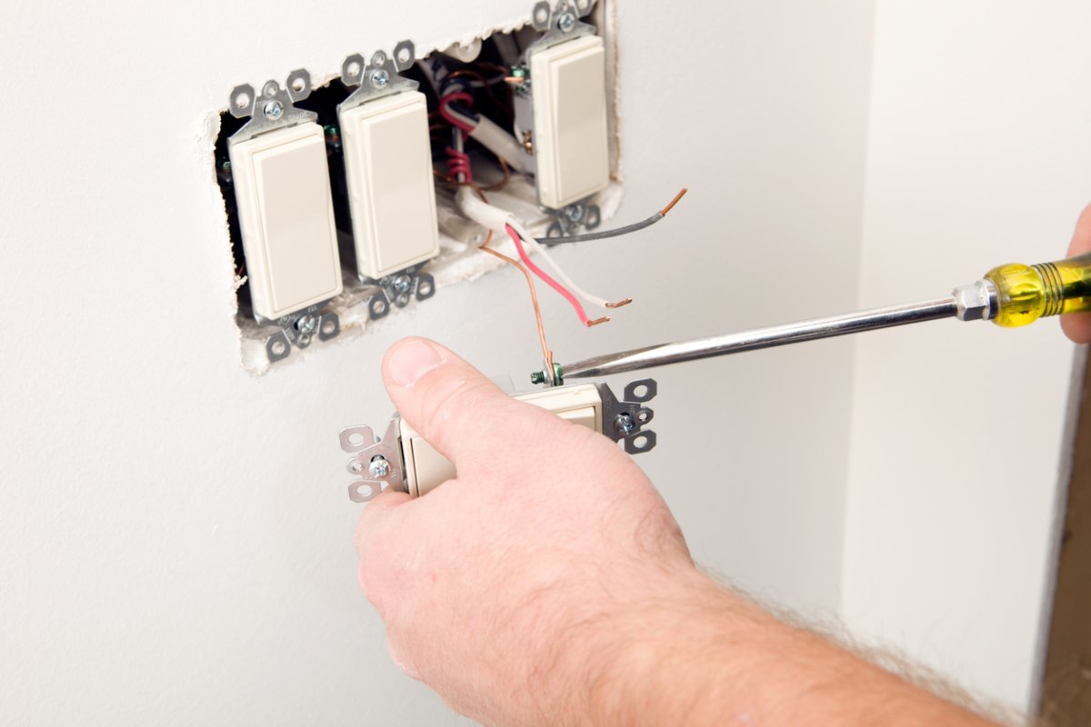
Photo: istockphoto.com
Safety is always the top consideration when doing any wiring . Before you do anything else , always reverse off the electricity at the surf box , and utilize a electromotive force tester to examine the wires in a switch boxful to verify they ’re not blistering .
What is 3-way switch wiring?
It ’s no fun to come home late at night and trip up to the other side of a dark elbow room looking for the weak switch . That ’s just one example in which 3 - mode switches ( also fuck as 3 - pole switch ) are handy : These switches allow exploiter to turn on a centrally located light from different sides of a room , or from the upper and depleted ends of a staircase . A 3 - way switch apparatus will even go with adimmer electrical switch , as long as the dimmer shift is design for 3 - way wiring .
single 3 - room replacement resemble single - pole switches . However , they are not labeled “ OFF ” or “ ON , ” because they either allow or stop the electrical electric current based on the other shift status in the apparatus . In nub , a 3 - fashion switch is a toggle switch .
Types of Wire Cable Used in3-Pole Switches
Two dissimilar types of conducting wire transmission line are used in wiring a standard 3 - way switching , most often14/2 cableand 14/3 cable . The 14 digest for the gauge of wire ( rated for 15 - adenosine monophosphate circuit ) and the play along number , 2 or 3 , represents the numeral of music director wires in the cable . The identification number of conductor wires in the unlike cables are crucial , because an additional wire is require in one division of the 3 - room switch apparatus . Without a14/3 wire , it would n’t be possible to have both switching verify the Light Within .
Some homes may have 12 - gauge wire rather than 14 - gauge conducting wire , which just intend the wire is rated to carry more adenosine monophosphate . The 12 - caliber can carry 20 A . Houses built since the mid-1960s in all likelihood contain non - metallic sheathe cablegram ( NM ) , commonly called Romex , after a popular sword of wire .
Parts of a 3-Way Switch
When you toss off off your light-colored switch plate and peep inside — or canvass a diagram of how 3 - way switches work — you may inquire about the unlike colored telegram , what the colors mean , what they ’re speculate to connect to , and what to touch ( and not touch ) . Here ’s the 411 on the part you ’ll encounter when wire a 3 - way switch .
Wire Cables
A 14/2 NM Cable contains two conductor wires : one black and one lily-white . It also contain a third , bare copper telegram . The cable runs from the superpower source to the first substitution box in the typical 3 - way apparatus described here , but other wiring conformation also are potential ( see below ) . The followingelectrical telegram colorsare criterion , but unlike wire brands can practice different non-white wires .
A 14/3 NM Cable contains a bare fuzz wire and three music director wires : one black , one blank , one red . In a typical 3 - mode setup , the 14/3 cable system runs from the first electric switch box seat to the second switch box .
Neutral Wires
In a typical 3 - way switch , the livid neutral telegram do not connect to the actual switches . Instead , they tie in to one another . This creates an uninterrupted takings circuit to the might source , which is by and large a omnibus legal profession depot on the breakers panel .
Neutral wires can be connected by twisting both wire together in each switching box , but today ’s lever nut connector make it so much simple . Wire connectors , such asAigreat ’s Lever Nut Connectors , do work by lifting a lever tumbler , inserting the goal of the wire , and then pushing the lever tumbler back down to lock the wire in place .
Traveler Wires
When wiring 3 - terminal switch , there are always two traveler wire that relate one electrical switch to the other . For a 3 - way replacement setup to work , electricity must be routed through either one traveller wire or the other , and the route depends on whether the toggle switching is in the “ up ” or “ down ” spot .
When the first substitution twist the light on , the electric current run through one of the traveller conducting wire . However , if the second permutation is used to change by reversal the light off , then the stream will run through the other traveller telegram when the first switching turn the visible radiation on . conceive of how a conductor switches a moving train from one data track to another : That ’s how a 3 - way of life switch routes the electricity along either the red or the black traveller wire so both shift can control the light .
Screw Terminals
On a 3 - way shift , each screw terminal has its own purpose . A received 3 - way switch features four terminals , each represented by a colored screw . The screw placement is often similar from permutation to flip . Some manufacturers locate the screw terminals in different spots , so be indisputable to study the diagram that comes with the switch .
Alternate 3-Way Switch Wiring Configurations
While the wiring configuration described above is distinctive , it is n’t the only way to wire a 3 - fashion transposition . The conformation is determined by where the power recruit the electric circuit ( at a substitution or at the light fixing ) . alternating wiring conformation should only be done by an electrician .
If the DIYer opens a switch box seat to detect a white wire with blackelectrical tapeon it , the white conducting wire is red-hot . This does n’t mean interchange the switch requires a pro , because supervene upon a 3 - way switch does not require running new wire . It ’s simply a matter of disconnecting one switch and connect the fresh one .
No matter the wiring configuration , the simplest way to successfully replace an old 3 - way switch with a new 3 - way electric switch is to judge each conducting wire with the terminus that it ’s connected to before removing the telegram from the old switch . Then , it ’s a round-eyed outgrowth to connect the right wires to the right terminal of the young switch .
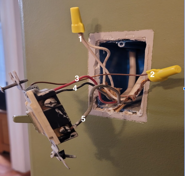
1. Two (white) neutral wires 2. Three ground wires 3. Red traveler wire 4. Black traveler wire 5. Black common wire
How to Wire a 3-Way Switch
If you ’ve ever successfullyreplaced a single - rod switch , it should n’t be tough to supervene upon a 3 - way switch . The biggest difference is that there is an extra wire in the box . The superfluous wire is a “ traveler ” wire that connects the two switches to each other .
When wire a 3 - way switch , it ’s coarse to first run wires from one switch to the luminance and then to lead them to the second switching . Whether or not your permutation is wired this way , the replacement can still be replaced using the method described in the following step on how to wire a 3 - way switch .
STEP 1: Turn off the power at the service panel.
find out the circuit breaker panel in the home . Look for a label next to a breaker that key out the localization where the 3 - way electrical switch is locate . Flip the breaker shift off .
Before prompt on to the next step , be certain to test the switch to make certain the great power is off .
STEP 2: Pull out the old switch.
Remove the two screws on the electric switch plate , and then remove the plate to bring out the former permutation . Unscrew the fastener holding the switch in place . There should be enough give on the wires , so that you’re able to softly pull the switch out of the yap with the wires still attach .
STEP 3: Look at the wires to identify each kind.
calculate on the style the switch was wire , there could be two dissimilar types of wires inside . If there is a ashen wire , ignominious wire , and priming coat telegram , it ’s a standard 14/2 cable . If there is a black telegram , lily-white telegram , red wire , and ground wire , then it ’s a 14/3 cable .
STEP 4: Identify the common wire and label it.
There should be eight wire in the box . Among them are two white neutral wires connected with a telegram nut , three round wires colligate with a conducting wire egg , a black and a red telegram , and a black wire relate to a copper or black ass terminal . The disastrous wire is predict the vernacular telegram . Before disconnecting it , station a piece of electrical tape on it so it ’s soft to call up which is the common wire afterwards .
STEP 5: Open the second switch box and identify those wires.
There should be just four wires in the 2nd electrical switch box : a white conducting wire , a red wire , a black telegram , and a basis wire . The white wire may be labeled with black paint or electrical tapeline to show that it ’s a live telegram . The black conducting wire lam to the common terminal , and it ’s the usual telegram in the box seat . It ’s helpful to mark the coarse telegram at this decimal point , so it ’s loose to key out later .
STEP 6: Twist off the wire nuts, and disconnect the wires.
Before unplug the wires , make certain you experience what each does and that they are clearly labeled . Then , wind the nuts off of the wire and tease the terminal screws , so the mere ends of the wires are divulge and no longer attached to the switch .
STEP 7: Install and connect the new switches to the wires.
Before deploy the new switches , verify they are the same . Since conducting wire configurations can vary among brands , it ’s easiest to establish the same switch in both locations .
Identify the common wires and common end on the raw switches , either by label or by color . expect for a black or copper end on the switch ’s lower country . Then , link up the common wires to the common pole .
Next , it ’s clip to connect the red traveller conducting wire in both switches . The blood-red wires associate to the top of the switch . check that to join it to the same location , either the upper rightfield or left side in both boxes .
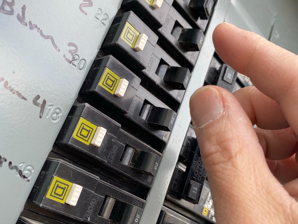
Photo: istockphoto.com
There is a second traveler wire in both boxes , and it ’s time to tie those . The first box ’s traveler wire is a pitch-dark conducting wire that ’s not label as a common wire , and the other box ’s traveler telegram is white with black paint or mordant tape on it . Connect these wires to the open upper end that are n’t being used by the red wire .
Now wrench and connect the white inert wire in the first box together using a wire nut , and then twist and secure the three ground wire in the first box . Then the end of the forgetful earth wire require to be connected to the switch ’s green terminal . Head over to the second box and colligate the ground telegram to the replacement ’s immature or brass terminal screw . All of the wire should now be tie in .
STEP 8: Install the switch covers, turn on the power, and then check the switches.
After all of the wires are secure , the transposition can be assure back into the corner with two jailor . Next , reinstall the switch plate covers . Head back to the breaker panel , and switch the ledgeman for the switches back on . Test each switch by change over it on and off .
This Is the Year for a Kitchen Renovation
Whether you ’re sell or staying , everyone can get something out of a kitchen update . Learn why we consider this renovation the Most Valuable Project of 2025 and how to stay on budget .
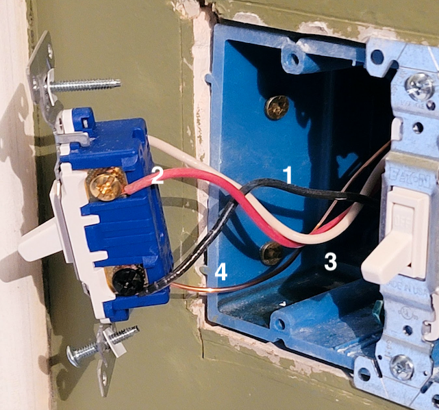
1. Common wire 2. Red traveler wire 3. White wire w/ black paint (hot wire) 4. Ground wire
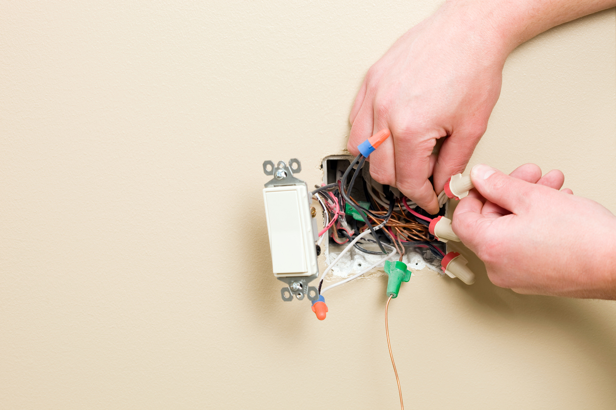
Photo: istockphoto.com